2018-08-11
I looked at different fuselage constructions methods and ended up going with 0.016 inch aluminum sheet over aluminum stringers. It is the lightest and cheapest of all options I considered at 0.36 lb/foot and around $7/foot not counting fasteners. The diameter of the fuselage is 6 inches. I had already planned on using the aluminum stringers but I hadn't made the decision yet on what skin to use. Aircraft Spruce has 2x2 foot sheets of 2024-T3 which is a convenient size and ships flat. I'm using flush countersunk pop rivets (AACS-04-02) in the tank sections where access is not required. Since the sheet is so thin, it is dimpled and then there is a countersink on each hole in the stringers. I made some drill jigs out of 1/4 aluminum angle bracket and a #30 slip fit bushing insert. The holes drilled separately in the stringers and skin lined up for the most part with just a few holes that I had to drill through at assembly time. For the sections where I need access such as the engine bay and in between tanks, I'm using MS21075L06N floating nutplates and MS24693 countersunk screws.
The test part I made came out OK but I cut the sheet a bit short so it doesn't completely wrap around. As a result, it has a larger gap and smaller edge margin on one side than I intended but still works. I don't have any sheet metal equipment (or room to put it) so I signed up for a membership at the local makerspace where they have a stomp shear, slip roll, and tons of other goodies. The shear worked OK but the slip roll had 3 inch rollers and wouldn't roll a 6 inch fuselage since the 0.016 sheet has too much springback. Instead, I got a section of 1.5 inch schedule 40 PVC pipe which is just about the right OD for making the bend. I taped down one edge to the pipe with some aluminum tape and used elbow grease to roll the sheet around it. It generally worked but the rolled part had sort of a flattened side. I also discovered that you can cut 0.016 sheet with a utility knife, making several passes and then breaking the edge, so I may not need the shear either. I considered using NAS1330A06 rivnuts in certain areas but even when installed properly, they have a tendency to loosen making it impossible to remove the screw without drilling it out. There is a keyed version but I decided to go with the nutplates instead. Here are some more pictures of the test part.
The next task is to design the fin attachments and the access doors.
2018-03-11
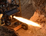
I finally got a chance to run the static test of the flight vehicle this weekend. From a vehicle perspective, it was very good and I'm ready to move forward with getting it ready to fly. However, from a test operations perspective, there were a couple of issues.
The only vehicle issue was a hold during the countdown sequence at T-2 seconds due to low igniter CDI current sense. I had not seen this issue in previous testing so the timing must have been marginal and apparently I just got unlucky this time. After pressurizing the tanks, the state machine enables power to the RCEXL CDI module, waits 100 ms, then checks to see if the current is at least 2/3 of the expected steady state value. The data shows it was at about 50% of the expected value when it was checked so it transitioned to the hold state. However, the next sensor data packet was just above the minimum so a longer delay would have worked. The root cause is a design issue of that portion of the state machine since the averaged data used for the CDI check is only sent at 10 Hz and it's very unlikely that it should ever have enough time to pass with only a 100 ms delay. The fix is to increase the delay before checking the CDI current. When the hold occurred, I manually turned the CDI on, verified the data showed the expected value, then issued a state machine jump back to the same state where it passed the check and continued the countdown. I had added the ability to manually jump to the state machine a couple of months ago so that paid off in this case.
Test operations wise, there were two issues. The first is that I had trouble getting a full LOX load, even with the modified sequence of closing the vent valve before closing the dewar. The tank should hold about 17 seconds of LOX but it ran out at around 12 seconds which caused the rest of the fuel to burn outside the chamber until I manually issued an abort. I built my test pit 4 feet below ground with berms on all sides so it was contained without issues. When loading the LOX tank, it seemed to take much longer than it did with the LN2 tests. I had ordered a low pressure dewar (25 psi) but when I picked it up and got home, I noticed they gave me a high pressure dewar (230 psi) and the pressure had already risen to 200 psi. I vented it for about 30 min and got the pressure down to around 40 psi but I wonder if the bulk temperature had already risen enough where an ambient pressure transfer would lose a significant portion of liquid. All the transfer hoses and the vehicle tank had new polyethylene cryo-rated foam so in theory that should have at least been better than before. I loaded LOX until liquid squirted out the vent, just like I usually do on past tests and it seemed full. The elapsed time between the completion of the LOX load and start of the test was less than 5 minutes. I did notice that the fuel line that passes close to the bottom corner of the LOX tank did not get as cold as it did during LN2/water testing (it froze during one of the tests last year). That could either be due to the better insulation or because LOX is somewhat warmer than LN2. I wasn't too worried since kerosene has a much lower freezing point than the water I was testing with.
The other test issue was with the helium pressure. I thought I had enough high pressure helium on hand but when I loaded the vehicle helium tank, I only got it up about 2080 psi where I was hoping to load it to at least 2500 psi. This wasn't a showstopper as it just resulted in a thrust dropoff during the run with it starting around 252 lbf and dropping off to around 183 lbf at the end of the run (based on chamber pressure). However, it could have been easily prevented by ordering another 3500 psi helium cylinder prior to the test.
Despite the minor issues above, many other things worked well including the flight computer, data recording, sensors, plumbing, custom cryo valves and the ground support equipment. This was my first vertical test and I was wondering how the blast deflector with the 24 x 24 x 2 inch concrete pavers would work out. There was a significant amount of erosion on the first paver as expected, some at the first joint where it turned to the second one, and essentially no erosion on the third one. I didn't know how far the plume would spread out but from the photos, it looked reasonable compared to other similar setups. The vertical support was two 8-foot 8020 strut sections connected together and they worked OK but the butt anchors were a little loose after I took it down. Next time I'll use a splice plate. The videos and still photos turned out OK except for some obscuration due to dirt kicked up by the plume spreading out on the deflector. After the LOX ran out, a piece of tape on the igniter line caught fire and the LOX fill tube insulation melted due to the extra fuel that burned outside the chamber. For future vertical static tests, I'll add some shielding to protect the components above the engine.
|