|
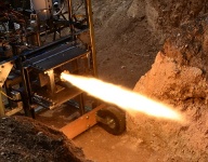
Here are the specs for the regeneratively cooled engine:
Fuel:
Kerosene
Oxidizer:
Liquid Oxygen (LOX)
Mixture ratio: 1.8
Thrust:
100 lbf
Chamber pressure: 200 psia
Chamber diameter: 2.16 inches
Chamber length: 3.44 inches
Nozzle throat dia.: 0.72 inches
Nozzle exit dia.: 1.22 inches
Injector pairs: 6
Fuel injection dia.: 0.038 inches
Oxidizer inj. dia.: 0.041 inches
Chamber temperature: 5400 Deg R (4940 Deg F)
Chamber material: 6061-T6 aluminum
Here is the complete design spreadsheet in
OpenOffice format and in
MS Excel format.
There were a lot of tradeoffs to consider in the design of the regen
engine. I had to reject many of the traditional design methods
(annular, helical, brazed tubes) because they were not feasible to
fabricate with my basic machine shop equipment. I made some conical
forms hoping to expand annealed copper pipe but it didn't work out too
well. The plan was to get the force the copper pipe over the mandrel
and then braze tubing around the outside in a helical pattern. My
attempts at brazing were less than useful however.
The design I settled on is a solid wall chamber with cross-drilled coolant
passages. The hardest part was coming up with a scheme that would
keep the wall temperatures at a reasonable limit for aluminum.
According to MIL-HDBK-5, 700 degF is about the useful limit of
6061-T6. At that temperature the yield strength is 8% and the ultimate
strength is 10% of the room temp values. This requires significantly
thicker walls than you would normally require but it turns out that the
required wall thickness, 0.05 inches at the throat, is about the
minimum I would feel comfortable maintaining while cross drilling
holes.
A traditional one or two-pass coolant tube design required really tiny
holes that I would never be able to drill. Instead, I went with just
one "tube", alternating up and down in 10 total passes (see the drawings
for an image of the solid model). This allows for
a fairly large coolant hole since the cross sectional area is sized
for the entire fuel flow. This keeps the velocity high enough for
cooling with a total pressure drop across the coolant jacket at a
manageable 85 psi. The approx 0.14 inch diameter
holes should be fairly easy to cross drill. For simplicity, the same
hole diameter is used throughout the chamber, converging, and diverging
sections of the nozzle. There will be a cap at the nozzle exit to
enclose the tube reversal slots. The injector face will serve the
same purpose at the other end of the chamber. Grafoil sheet serves as
a pretty good high temperature gasket. The holes on the outside of
the chamber for the converging portion of the nozzle will have to be
plugged somehow.
The Analysis section contains the final results of many thermal
analysis runs, using the evaluation version of Mayasim TMG. Since
everything in the engine is symmetrical, you only need to model a
single tube. Also, I found that you don't need a very fine grid for
thermal analysis. Once I figured out how to apply the boundary
conditions in TMG, it went pretty quick.
The single tube in 10 passes complicates the analysis
somewhat since I had to evaluate the heat transfer at different
chamber wall and coolant temperatures. Since practically
all of the material and fluid properties vary with temperature, this
proved to be pretty complicated. The thermal analysis shown is a run
with properties calculated at an average temperature.
Some comments on the design parameters:
The pressure drop across the cooling jacket varies significantly
depending on the temperature the coolant properties are evaluated at.
After considerable calculation, I modified the spreadsheet to
use average, min, or max temperature properties where appropriate. It
was surprisingly difficult to find fluid properties of kerosene at
various temperatures. I'm well within the bulk coolant capacity of the
fuel but I'm a bit worried about the bulk temperature of
the fuel (325 degF) at the cooling jacket exit causing deposits on the
cooling tube walls. I plan to use Jet A for the fuel so I have good
access to the thermodynamic properties.
I took credit based on NASA SP-125 for thermal resistance from the carbon
deposits on the walls due to kerosene combustion. Testing
with embedded thermocouples will show whether this was a reasonable
assumption or not. I also found that 1D thermal analysis was quite
a bit more conservative than necessary. I played around a bit with
a fin factor (described in Hill & Peterson, p. 430)
that takes into account the fin-like geometry of a
coolant tube. I was able to select a fin factor based on my geometry
that, when applied to a 1D analysis, almost exactly matched the 2D TMG
analysis. Since I can't link the TMG analysis to the spreadsheet,
this made the spreadsheet a lot easier to use.
For the injector, I'm using 6 unlike split triplets. There is a good AIAA paper that
describes the split triplet in detail - "Effect of Momentum Ratio on the Mixing
Performance of Unlike Split Triplet Injectors", Journal of Propulsion and
Power, Vol. 18, No. 4, July-August 2000. The split triplet is attractive for me from
a fabrication point since my oxidizer holes are in the middle and this keeps
them from pointing toward the wall as they did in my uncooled chamber.
I'd like to put additional fuel holes near the chamber walls but the holes
are already getting too small as it is. I don't have good heat
transfer estimates for the injector face so that is definitely a
potential weak point. There's tons of great material in the NASA SP papers
regarding injector design. Some other good references are the NACA RM
and TM reports. The Swiss Propulsion Lab
has an excellent collection of links in the publications section.
|