2006-10-03
I'm starting to see a pattern here... do a rocket test, get a new job and
move. That sure interrupts the rocket progress for a while. Anyway, I've
been able to spend some time analyzing the data from the last runs so not
all the time has been wasted. I'm planning on running the regen engine
again in another month or two assuming the work schedule cooperates.
Here is a summary of the recent tests with the regen engine:
-
Design thrust = 100 lbf, actual = 68 lbf
-
Design chamber pressure = 200 psia, actual = 142 psia
-
Design Cf = 1.21, actual = 1.17
-
Design Isp = 217, actual = 147
-
Design c* = 5464 ft/s, actual = 4057 ft/s
Note that the design Cf, c*, and Isp above were recalculated using the actual
chamber pressure and mixture ratio. In general, Cf is a indicator of nozzle
efficiency and c* is an indicator of combustor performance.
The nozzle efficiency only looks low by about 3% so I'm suspecting poor
mixing and combustion. With this new injector, I kept the spray pattern
in the center to keep it away from the walls so maybe I need to spread out
the injector orifices and redistribute them more across the face. However,
the holes are already pretty small as it is so it will be hard to use more
holes for a 100 lbf engine.
For the next set of runs, I'm going to make the following changes:
-
Use helium instead of nitrogen for pressurization. Some people
have reported significant performance gains when switching from nitrogen
to helium because LOX tends to absorb the nitrogen, making
it "fluffy". I'm really hoping this is a large part of the problem.
-
Use a flowmeter to measure the fuel flow. I had such a huge pressure
drop in the cooling passages (230 psi) that just the variation in
temperature could have had a significant effect on the mixture ratio.
I'd like to also measure the LOX flow but a cryogenic flowmeter is a
bit out of my price range right now...
I'm also in the middle of doing some upgrades to the test stand. I'm
replacing the homemade air actuated fuel valves with some "real" actuated
ball valves because of some stickiness that has been bothering me for a
while.
2006-02-28
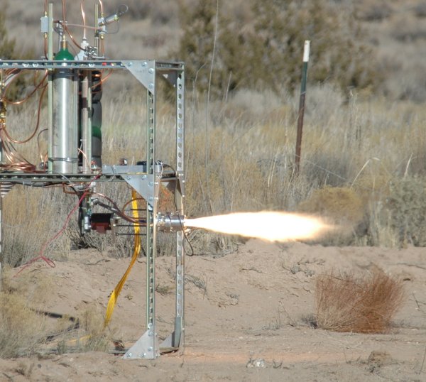
Successfully fired my first regeneratively cooled engine last weekend!
All the pictures and videos are in the
Regen Chamber Tests section.

The thrust was a little low (70 lbf instead of 100 lbf) but it ran twice
for about 30 seconds each without melting. I must have overpredicted the gas side heat
transfer coefficient because the measured wall and fuel temperatures were
well below my design point. I'm a bit confused on the thrust because I
thought I did a better job this time predicting the required tank pressure
to give the proper propellant flow rates. By the way, I remeasured the
injector discharge coefficient as 0.84 for the LOX holes and the combined
pressure drop across the fuel cooling passages as a whopping 208 psi. Since
I have plenty of margin for cooling, I should be able to cut that down next
time and get a more reasonable pressure drop.
For this test, I used Jet-A where last time I used K1 kerosene but I was
under the impression that they were essentially equivalent. I went back
and looked at my equations for the uncooled engine and I came up with a
value for the density of kerosene of 36.21 lbm/ft^3. I have no idea where
I got that value - as a result, for the uncooled engine, I pumped 8.06
in^3/sec of fuel. This time, I had good data for Jet-A at different
temperatures and the equations resulted in a target of 6.53 in^3/sec.
If you recall, on the uncooled engine, I had pressure droop in the regulators
which caused a proportional drop in the chamber pressure and thrust.
This time however, I figured out the droop in advance and corrected for it.
So, the only thing I can think of is that last time my design was far
enough off that it worked out but this time, I hit my flow rate targets.
That tells me that there might not be enough volume in the chamber for
complete combustion. For the uncooled engine, the cylindrical chamber
volume was 15.6 in^3 and for this regen engine, I reduced the chamber
volume to the minimum (12.7 in^3) to try and help out with the cooling
problem. Next time, I'm installing a flow meter in the fuel line to so
I can measure the exact flow rate.
I ran 3 total runs, one false start (Run 0) and two actual firings (Run 1
and Run 2). On the false start, I had too much of a fuel lead and it
burned itself out after ejecting the ignitor from the chamber. It then
proceeded to fill up with fuel and LOX - it's a miracle I didn't have a
really bad hard start. I switched the valve sequencing around to lead with
the LOX first and the next two runs started up nicely. That is the one
disadvantage of an external ignitor - it is simple but once it gets ejected,
you better hope the fire inside is going.
The first good run (Run 1) was very stable. It actually only ran for
about 25 seconds because it ran out of LOX 5 seconds early. I guess I
spent too much time after filling the tank before I fired it and too much
boiled off. The second good run (Run 2) was not nearly as stable.
It ran for 30 seconds but had several steps in thrust
during the run. I didn't tear down the engine
between the runs (I only cleaned the LOX lines) so I suspect some of the
sooty junk migrated up into the fuel injector and clogged one of the holes.
During the teardown, I found black soot and small particles in the fuel
injector face cooling passages. About halfway through Run 2,
the flame changes shape and the thrust picks up by about 1/6th of the
total thrust (there are 6 fuel injector holes).
Even after almost 60 seconds of hot firing, the engine shows no visible
signs of wear, even around the injector orifices or chamber pressure tap.
In fact, you can still see the tool marks on the walls. Assuming I can
clean out the cooling passages, I should be able to run it again and try
to figure out why the thrust was so low.
The video cameras I used were very sensitive so I purchased a 2-stop
neutral density filter to try and cut down on the intensity but the CCD
was still saturated. I wasn't too pleased with the video quality but the
still images came out good. I was caught off guard by a problem I ran into with
the IRIG video overlay devices. When run off of a generator, they had trouble
locking on to the video signal and the IRIG time code just rolled vertically.
Since I discovered this the night before the test, I hooked up a 300 W car
power inverter to supply 120 V to the time code power brick. Then, I
connected the power inverter to a 12 V ham power supply which was connected
to the generator. I guess that crazy combination provided enough filtering
to fix the problem. Next time, I'm getting one of those fancy UPS units
that have power conditioning built-in.
2006-01-16
Performed cold water tests
on the injector this weekend. The measured discharge coefficient was
Cd=0.78 but I'm going to repeat the tests with a better pressure
measurement. I took measurements at tank pressures of 10, 20, 30, and 40 psi
but at these low pressures, the cracking pressure of the check valve causes
the tank pressure to vary by about 5 psi during the run. I think it will
work better if I just hook up a garden hose and a pressure gauge/transducer
and bypass the test stand hardware. I suspect the actual Cd is about 0.8
to 0.82 but I have to prove it.
The flow from the orifices looks pretty clean but I was puzzled by some
strange behavior from the central LOX holes. All 6 holes seemed to behave
like they had a
misalignment of about 15 degrees in
the same direction and completely missed the fuel jets. I
initially thought maybe there was a vortex forming in the small plenum just
above the LOX holes but you'd think the holes would "straighten" that out.
A visual inspection showed the holes were much straighter than the flow
coming out of them. Just for kicks, I took the same drill bit I used for
the holes and ran it in and out by hand a few times and presto!
The holes flowed straight.
I'm still puzzled by that one. I guess I didn't clean up the holes
properly after drilling them.
Calculating the pressure drop in the injector coolant passages took a
little bit of thought. Since I couldn't separate out the drop between the
coolant passages and the fuel orifices, I assumed the Cd was the same for
the LOX and fuel holes. Since they are about the same size holes and
drilled from the same setup, this should be close. I then calculated the
estimated pressure drop across the orifices and from that, I was able to
back out the pressure drop in the injector coolant passages (~22 psi vs.
my design prediction of 20.6 psi). Again, these numbers may change when I
re-run my Cd measurements in a few days.
I also went ahead and cut the Grafoil gaskets that I'll use to seal between the
injector and chamber,
between the chamber and end plate, and to close out the
holes for the cross-drilled coolant passages. The Grafoil
is really cool to work with - I used a crafter's circle cutter to cut the
outer/inner diameters and a regular hole punch to cut the bolt holes.
Part of the time this past month was spent working on the electronics
portion of the test stand. I replaced the little switching power supplies
with some linears and put all the remote equipment (PXI chassis, SCXI
chassis, relay box, and power supplies) in a
portable rack mount chassis to make it easier
to move everything around. I still need to make some
cables to connect the PCI IRIG card with the PXI chassis so I can
synchronize the IRIG time video overlay with the DAS data. Last time I used
a CompactPCI IRIG card in the remote chassis but I don't have access to
that card anymore.
|

