2022-01-25
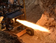
I posted new photos, videos, and data of the Rocket 1 launch in the Tests section. Several people asked what the goals were for the test and I have to say the main goal (and actually of the entire project), was to launch a liquid rocket and recover it successfully. I wasn't necessarily targeting a specific altitude but I had done some RASAero II and OpenRocket simulations that were showing around 15k ft if I had been able to load 15 sec of propellant. Achieving 10,800 ft is still plenty good enough for me and helped to ensure we could actually find the rocket afterwards. I loaded 16 seconds of fuel and a full LOX load (16.9 sec in theory) but it was expected that boiloff would reduce it somewhat. I loaded extra fuel to ensure that I didn't end with LOX as that would have certainly melted the engine. I thought I was working fairly fast after LOX load to get to launch but from looking at the video, around 6 minutes elapsed between LOX load and when the launch occurred. During that time, about 1/3 of the LOX boiled off and I got an engine run time of around 10.5 seconds. There was insulation on the tanks which helped somewhat but I should have closed the LOX vent valve to keep it from boiling off. However, I think I bumped the rocket too much and dislodged the umbilical which necessitated a trip back to the pad to reseat it prior to launch. Doing that with a vented LOX tank was much safer. I had planned to use a spring scale to measure the rocket weight to ensure the LOX tank was actually full. During some ground tests, there were a couple of occasions where I thought the LOX tank was full but it really wasn't so I wanted to weigh the rocket on the pad to ensure it was full. However, there was too much friction with the rail (+/- 5 lb) so the scale was useless and I removed it from the tower. I loaded LOX until I saw liquid squirt out the vent and that appeared to be good enough. I wish there were some reasonable solutions for LOX level sensing.
Launch preparation in general was smooth without any significant issues. We arrived Friday afternoon at FAR and performed vehicle checkouts along with a test fit on the rail. The first casualty from the trip to the site was that one of the spring loaded switches on the power panel fell off and was rattling around in the avionics bay. The other casualty was that the screws that hold together the two-piece rail guides were loose. Those must have been the only threaded fasteners in the whole rocket that I didn't use threadlocker on or weren't locking fasteners. During the test fit on the rail, I realized there was very little clearance between the magnetic umbilical disconnect and the rail. If I moved the rocket around too much, the rail would knock off the disconnect which I think is what happened prior to launch. This could have been fixed by repositioning the rocket-side portion of the disconnect but that wasn't practical at the last minute. I was worried about the ground-side portion of the umbilical getting snagged on the fins so I rigged up a bungee to encourage the umbilical to pull away from the rocket at liftoff. It was difficult to get enough tension on the bungee to pull it away without also disconnecting it. I used SS fasteners to hold the magnets which I think reduced the effectiveness - normal steel screws seemed to amplify the magnetic force between the two halves. One thing I added to the rocket based on ground testing was a GN2 purge for the LOX fill and vent valves. During some repeated cold tests with LN2, the LOX vent valve froze up due to condensed moisture collecting in the open bearings of the ball valve. The fix was to encase the vent valve in a plastic bag and run some GN2 through it. I added a plastic hose QD port on the side of the vehicle and connected it with some tubing to a GN2 tank using a low pressure purge valve. Inside the vehicle, I also routed the GN2 to the avionics bay and to the engine bay for good measure.
Saturday morning was spent performing final packing of the parachutes and double-checking telemetry for both the primary and secondary (TeleMini) streams. I decided to load the consumables in order of 1) GN2 for the pyroless recovery system, 2) Fuel, 3) GHe, and finally 4) LOX. The pyroless system has nearly zero leakage so I wanted to do it first. The fuel was transferred through a Jiffy-Tite QD fitting using a Harbor Freight siphon pump. During proof and leak checks back at home, the high pressure helium plumbing had a leak of around 100-200 psi/hr so I wanted to do that right before LOX fill. I was unable to obtain a high pressure GHe cylinder in time for the launch so had to settle for a standard cylinder (2000 psi) and then top it off to 3000 psi with a high pressure GN2 cylinder. There is always a concern about using GN2 for LOX pressurization since it tends to dissolve in the LOX and I may have seen some issues related to that. During the hot-fire tests in 2018, with pure GHe, the LOX tank stabilized at 382 psig prior to the test and then drooped to 332 psig at the start of the run (before the GHe started dropping). During the flight, the LOX tank stabilized at 364 psig and drooped to 305 psig at the start of the test. That is about an 8% reduction in LOX tank pressure which may have accounted for the 5% reduction in chamber pressure observed during the flight. I'm a bit puzzled though - even if the mix of GHe and GN2 was dissolving in the LOX prior to the test, there wasn't any significant flow so the regulator should have stabilized at around 382 psig. When I performed the proof and leak check at the end of Dec 2021, the no-flow LOX pressure was at around 370 psi. I expect there is some variability in the setpoint and I seem to recall when I first configured the regulators a few years ago, the setpoints weren't as repeatable as I expected. In any event, during the flight, the fuel tank was 2% lower than the 2018 hot fire test and the LOX tank was 8% lower. Assuming no significant shifts in the transducers or onboard data system, the measured chamber pressure (via the igniter) was also lower by about 5% which means the thrust was also low by 5%. Whether the low LOX tank pressure and thrust were caused by the mix of GHe and GN2 or whether it was a regulator setpoint issue, I think it was a good idea to supplement the onboard helium tank pressure with high pressure GN2. Otherwise, the chamber pressure and thrust would have started off slightly higher but would have rapidly tailed off during the burn.
There weren't any showstopper problems on launch day. One issue I had with filling the onboard helium tank is that the core depressor pin on the Schrader 556 strut coupler was very hard to turn when pressurized. I'm using an AN6287-1 strut valve on the rocket side for the helium port so you need a way to depress the strut valve when filling. I had seen the same thing during proof testing at home, just though I'd mention it here. Another issue is that I had added a drain valve to the LOX fill plumbing to vent the hose prior to disconnect. I was using a McMaster brass needle valve (cleaned for O2) but the valve froze up and I couldn't turn it with my big padded gloves. After about a minute, I was getting anxious to disconnect the LOX hose since pressure was surely building so I pulled apart the QD that I had reused from the test stand which sprayed a fair amount of LOX toward the rocket. The LOX fill valve on the rocket was a bit hard to turn when cold so I had to use a larger flat blade screwdriver to close it after LOX fill. The helium access panel was held in place with a piano hinge and four pop rivets but while struggling with the strut coupler, I managed to break all the pop rivets and the access panel fell off in my hand. I placed it back on, secured the two DZUS fasteners, and used aluminum tape to hold the access panel in flight. I wish I had placed the helium fill port lower on the vehicle - having to climb the launch tower and hold on with one arm made it difficult to make all the connections. Prior to the flight, I noticed my Yaesu TH-G71A HT died (wouldn't turn on) with any battery pack (even with AA cells), after working perfectly for over 25 years. It worked fine the week before the launch - go figure. I didn't end up needing direction finding to locate the rocket though.
Countdown proceeded as expected under control of the flight computer and the rocket lifted off without any launch holds. I stopped looking at data at T-3 so I could see the launch in person. Plus, there weren't any decisions I could have made on short notice anyway from the ground station. While the umbilical is connected, the ground station can send commands over Ethernet to the rocket and in flight, a portion of the frame is reserved for the flight computer to listen to commands from the ground. The main and drogue deployments were nominal (see below) so I didn't have to use that capability. Rick Maschek taped on a small camera to the LOX tank that was pointing down but it appears to have fallen off a few hundred feet in the air because of frost on the LOX tank keeping the tape from sticking.
I was concerned about the potential of drogue deployment shock to either rip out or damage the parachute mounting lugs. Assuming no wind at apogee and a 50 ft/s freefall, I didn't expect very much opening shock from the drogue (PIFCALC predicted 78 lbf) and the onboard accel data shows less than 0.5 g. Luckily, the wind was calm so there wasn't a significant horizontal velocity component at apogee. For the main descending at 15 ft/s and an assumed opening time of 2 s, PIFCALC predicted around 250 lbf and the onboard accel data showed about 7.1 g or 376 lbf. The main parachute was in a deployment bag and held in place by the main release mechanism, also a gear motor similar to the one used for the pyroless release mechanism, but stronger to handle the larger loads expected during main deployment. The main was folded per the Rocketman suggestion and the 5/8 tubular nylon shock cord was folded in bunches wrapped with blue painter's tape, 2 wraps for the first bunch, 4 wraps for the next one, and so on. From looking at the onboard video and accelerometer data, the first 56 seconds of descent was a wild ride and then it smoothed out abruptly for the next 71 seconds. It would have been nice to have an upward facing camera in the recovery bay to see what was going on, whether the drogue was tangled, just free falling, or something else was going on. The main was set to deploy at 1000 ft AGL, releasing the nosecone and drogue separately which landed a few hundred feet away. The drogue descent rate was higher than expected (78 ft/s vs. 50 ft/s) and also the main (21 ft/s vs. 15 ft/s) so I'm not sure what was going on with that. During descent, I was trying to determine the descent rate from TM data but it was difficult due to the noisy baro data and the confusing/incorrect GPS data. Fortunately, things settled down by the time the main was to deploy and that worked as expected. I had partially implemented a map display in my ground station software but I didn't get it completed in time so all I had was azimuth/elevation/distance to the rocket instead of a nice moving map display.
After examining the onboard pressure data, I suspected a calibration issue with the igniter chamber pressure transducer so I took a look at the X acceleration value from the ADIS16364 IMU. At 1.7 seconds after liftoff (well clear of the rail), the IMU reports an X accel of 3.41 g. I re-weighed the rocket when I got home and after taking into account the actual fuel and expected LOX loads, I calculated 69.9 lbm at liftoff. Subtracting the 2.0 lbm of propellant burned during the first 1.7 s, and using the thrust coefficient calculated from the test stand with the measured flight igniter pressure to obtain a thrust of 233 lbf, I get an expected X acceleration of 3.43 g which nicely matches the measured IMU value of 3.41 g. So it doesn't appear there were any large transducer shifts and the thrust really was lower than expected (233 lbf instead of 250 lbf). I then created a new RASAero engine file using the actual pressure/thrust curve from the flight data to compare the predicted and actual performance. Using the actual vehicle weight with the measured thrust curve predicts a max altitude of 10998 ft and 29.8 s to apogee with a max velocity of 777 ft/s. My primary flight computer reports a max altitude of 10883 ft, 30.8 s to apogee, and a max velocity (from pressure data) of 809 ft/s. The TeleMini reports 10875 ft, 28.7 s to apogee, and a max velocity (also from pressure data) of 756 ft/s. I had to guess a bit at the Kalman filter constants for the primary flight computer so apogee is a bit late and the velocity is a bit high. I had the recovery outputs from the primary flight computer and the TeleMini wired in parallel through optoisolators and it appears the TeleMini triggered the deployment at apogee. Even though I had a 6-axis IMU onboard, I ran out of time to implement the nav filter so I just recorded the 819.2 Hz IMU data for this flight to use for later development.
The GPS was essentially worthless during flight and when I got home to look at my code, I discovered the reason. There is a setting in the uBlox chipset to select the Dynamic Platform Model using the CFG-NAV5 message. I had intended to set it to "Airborne 4g" but I inadvertently left it in the default setting of Portable. I even had a TODO commented out in the code to properly set the mode but I glossed right over it when I did my final code review last month. So I'm sure the GPS receiver had no idea what was going on during ascent and it just gave up. Luckily, it came back to life right before landing and once I pointed the TM antenna downrange, I was able to get exact landing coordinates out of it.
As I mentioned above, the weather cooperated and no other serious failures popped up on launch day. In addition to good luck, I'd like to think at least some of the success lies with the extensive testing that I performed prior to launch and over the past few years. Tests included component and vehicle cold tests with water and LN2, engine/igniter tests, a full-up vehicle hot fire test, telemetry tests, parachute tests, numerous software unit tests, and rehearsal of the launch procedures. Each one of these tests uncovered something that could have been a showstopper on launch day so it was effort well spent.
Paul Breed asked me on aRocket what I would have done differently on the rocket so I though I'd include some of those answers here also:
-
I would have put the GHe (tank pressurization) and GN2 (pyroless) fill ports lower on the vehicle for easier access. I also would have made the access panel larger and probably out of a thicker material than the 0.016 inch thick skin. I already was going to place some aluminum tape over the DZUS fasteners anyway since they were kind of loose but when I broke off the access panel hinge rivets on the pad, I ended up taping over the entire panel. The access panel for the avionics bay worked much better since it was made out of the 0.1 inch thick fiberglass reinforced phenolic body tube. I think keeping the avionics switch panel fwd on the vehicle and away from the hot flamey stuff is still a good idea since a burn through of those wires would prevent moving the valves to a safe position in the event of a fire. A larger pressurization access panel would have also helped because at 3000 psi, the pin depressor in the strut valve was really hard to turn by hand.
-
I should have found a better place to put the telemetry antennas. They were in the recovery bay right next to the GPS antenna which required a special GPS antenna with a filter to reject the 900 MHz primary TM signal. The GPS antenna was supposed to be in the avionics bay (that's why it was fiberglass/phenolic) but the EMI from the flight computer swamped the uBlox GPS receiver.
-
I would have made the vehicle with a lower aspect ratio. The long skinny design has stability issues with wind, which fortunately wasn't a problem on launch day. The design though was driven from choice of modified oxygen cylinders so it didn't make sense to use a larger diameter body. I liked the oxygen cylinders though since they had a thick heel to put a boss port into and had a neck to use for an inlet fitting. If I had tried harder, I could probably have shortened the vehicle by 1-2 feet by making some custom manifolds instead of the ratsnest of tubing in the pressurization and engine bays.
-
As you probably noticed, I had a lot of fasteners. In several places there wasn't enough clearance to use a the floating nutplates so I cut off one ear and used JB Weld to make a Click-Bond style nutplate. The JB Weld cracked loose in many occasions during build so I should have used MS21061 one-lug nutplates with two fastener holes on one side. I really liked the floating nutplates though because they compensate for misaligned holes between the skin and stringers. And they allow you to take the skins on/off on the accessible bays without worrying about stripping out threaded holes in the stringers. A lot of people commented "wow, that's a lot of screws!" Yes, that's true but my informal survey shows skin/stringer construction to be the lightest option at 0.36 lbm/ft. The closest was PML CF ultralight with a 0.040 wall and that came in at 0.44 lbm/ft. I think the PSAS team had a honeycomb sandwich design that was super light though. The main thing you gain with a skin/stringer design is good access for tubes, wrenches, etc.and lots of places to attach things to the flanges.
-
I should have made the flight computer smaller and/or more easily removable. It consists of three boards, a power supply, a microcontroller board, and an analog signal conditioner board. Luckily I didn't have any failures but it would have been a real pain to get any of those boards out for replacement, especially since there's a shared heatsink for the TM transmitter and power supply board that ties into the airframe.
-
I used miniature Endevco/Kulite analog sensors with millivolt output but it would have been nice to have all digital sensors as I could have eliminated the signal conditioner board. However, using all digital sensors implies potentially using a common bus which could be a single point failure.
-
I was worried about FOD or dripping water from the LOX tank getting into the main valve servo. I made a makeshift rain cover out of some aluminum tape but it would have been better to completely encapsulate the gear assy and servo in some kind of 3D printed cover. There's not much room down there though.
-
I should have used 0.028 wall aluminum tubing instead of 0.035 tubing to save weight and make it easier to bend.
-
I considered adding externally powered solenoid valves to depressurize the tanks in the event of a flight computer failure but they were big and heavy. Luckily I didn't have a problem. My argument against it was that the helium tank was DOT rated and the LOX tank had a burst disc which would have self-relieved. The fuel tank could have remained pressurized though. If there had been an explosion on the pad, backup valves might not have helped anyway so the Winchester depressurization method might have had to be used.
-
A slightly longer recovery bay (by a few inches) would have made it easier to pack the parachutes.
-
Stronger magnets on the umbilical or perhaps a different design would have avoided that last minute trip to the pad. There was only minimal clearance between the ground side of the umbilical disconnect and the launch rail so when I was disconnecting the LOX fill hose, I likely bumped the rocket enough for the umbilical to pop off. I wanted to avoid the fins getting snagged on the umbilical so I had to add a bungee to pull them away at launch but that reduced the hold force that the magnets provided. The umbilical could have been placed near the base of the vehicle but then you have a lot of wires running through the engine bay which isn't ideal. There are other disconnect ideas out there I've seen but I just though the magnetic was kind of different so I thought I'd try it.
-
Software-wise, I wish I had completed the moving map (I ran out of time) so I would have had better situational awareness of where the rocket was during descent. I also should have double-checked the dynamic mode for the GPS receiver.
Overall, I achieved my primary goal of launching and recovering a liquid rocket. My next plans are to add active stabilization (with control surfaces, no gimbaling) to this rocket, then assuming I get that working, to build a larger vehicle. But I plan to take a few years off from rocketry and complete my RV-10 kit airplane. I'm sure I'll get bored after that and get back to the rocket.
2022-01-18
Well, that took a bit longer than I expected! Last weekend, I finally launched and recovered the 250 lbf LOX/kerosene rocket out at FAR, the Friends of Amateur Rocketry site in CA. I'm still organizing the photos/videos and analyzing data but the primary and backup altimeters show a max altitude of around 10800 ft AGL with a burn time of 10 seconds. The drogue deployed at apogee and the main was released at 1000 ft AGL as planned. All parts were successfully recovered intact which is a really lucky outcome. Yes, I did a lot of testing but sometimes you get either good or bad luck and apparently I ended up with good luck.
Part of the delay was that I purchased an airplane kit, a Van's RV-10 which I started on in Dec 2020. I worked on it through Apr 2021 and then I realized that if I didn't stop working on the airplane and fly the rocket, it would never fly and I would have wasted all these years of hard work. I was also working on my instrument rating last year which took a fair amount of time. I started back on the rocket in Sep 2021 and made a giant TODO list by month to get to an arbitrary launch date of Jan 15, 2022. I finished with about a week to spare which I used to start organizing and pack for the trip to CA. The remaining tasks included a Kalman filter for drogue/main deployment, onboard/ground data recording, procedures, general flight and ground S/W cleanup, and last minute testing/checkout. It's amazing how many tasks don't really need to be done when you start comparing priorities.
I posted a few pics in the Tests section for now but I'll add some plots, more photos, and videos soon. In the meantime, there are some nice videos on YouTube that folks posted of the launch.
For archived articles, check out the News section.
|